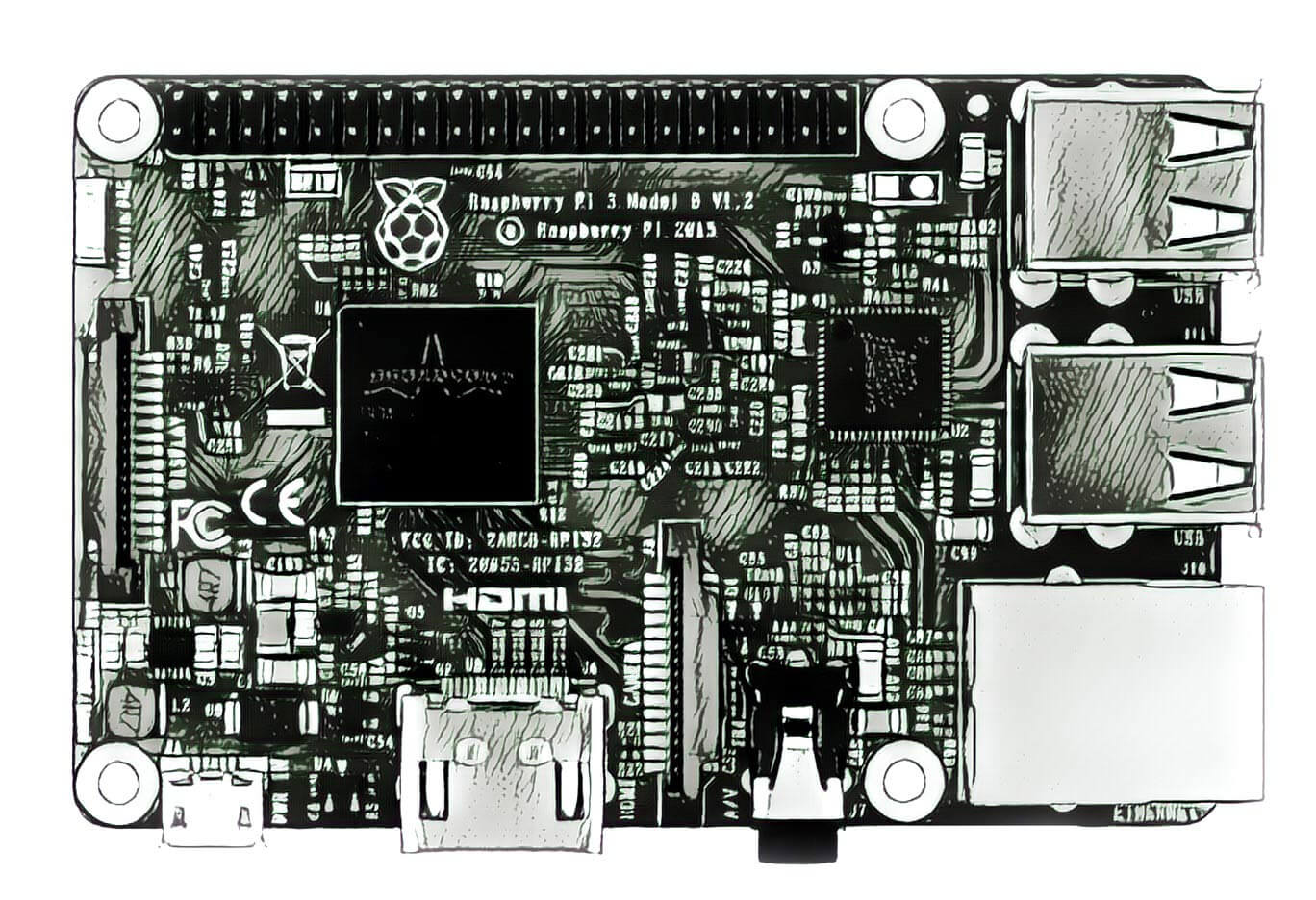

The GPIO pins can be used as both digital outputs and digital inputs. Serial UART Rx and Tx pins for communication with serial peripherals.SPI stands for Serial Peripheral Interface. The pins labelled MOSI, MISO and SCLK can be used to connect to high speed SPI devices. SPI is a similar idea to I2C but a different standard.I2C or IIC stands for Inter-Integrated Circuit. The pins labelled SCL and SDA can be used for I2C. I2C interface pins allow you to connect and control external hardware modules with just two control pins.The GPIO pins which can be configured as Input/Output and turned on/off via software. 8 GPIO pins – these are the true General Purpose IO pins that do not have a dedicated purpose but can be used for a variety of things such as turning LEDs on and off etc.The GPIO connector actually has a number of different types of connection on it. The 26 header pins can function as SPI, I2C, serial UART as well as providing +3v3, +5v power supply lines. The GPIO connector is made up of a 26-pin 2.54 mm (100 mil) expansion header, marked as P1 on the board and arranged in a 2 x 13 strip.

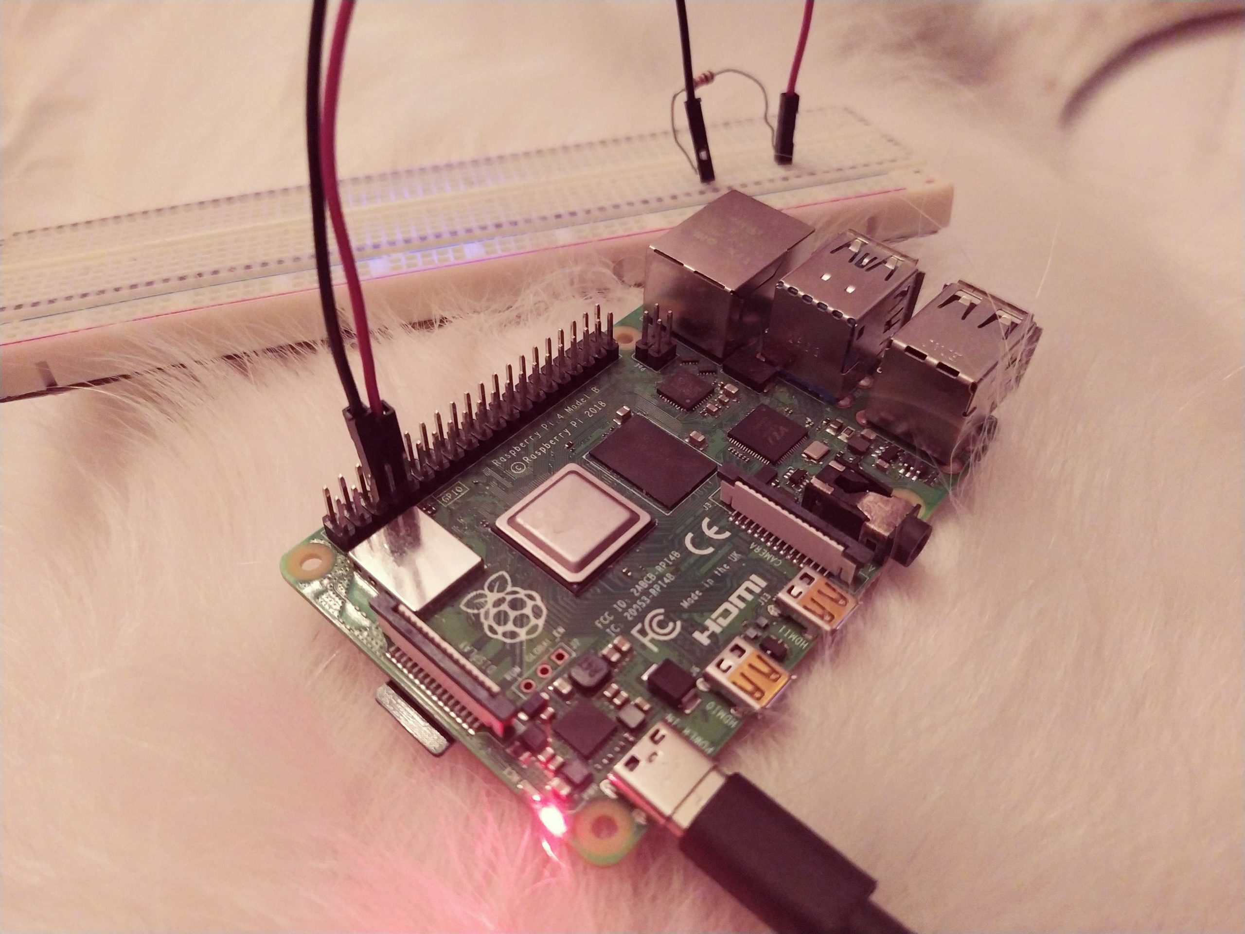
The GPIO pins on the Raspberry Pi can be found in on the opposite corner to the micro-usb power connector on the same side of the board. In order to do this we need to understand how the General Purpose IO header functions. It would be nice if we could control the LED by turning it on or off. This will light the LED, however, it will leave it permanently on. The long leg goes to the plus side and the shorter leg to the negative (or 0v) side. They have a long leg and a slightly shorter leg. Anything of higher resistance will make the LED dimmer. LEDs are diodes and as such only pass electricity one way. This means we need to make sure we put them in the right way round. Assuming a current of 20mA and a +3v3 supply it’s safe to use a resistor of 220Ω. Bear in mind that It is important to always use a resistor with LEDs to limit the current. If too much current flows through the LED, it will burn very bright for a short period before burning out, so a resistor is used to limit current.
#TEST SERIAL CONNECTION ON RASPBERRY PI PC#
What you type into the minicom terminal screen should appear on the serial PC terminal and vice versa.The easiest way to turn on an LED using the Raspberry Pi is to wire it up to the +3.3v or +5v pins of the General Purpose Input Output (GPIO) header and ground (0v), making sure to place a resistor in series with the LED and ground. Now run up minicom on the Raspberry Pi using Setup a connection using the serial port at 9600 baud. If you dont have this installed runĬonnect your PC to the Raspberry Pi serial port using an appropriate serial port adapter and wiring, then open Putty or a similar serial terminal program on PC side. In order you enable the changes you have made, you will need to reboot the Raspberry PiĪ great way to test out the serial port is to use the minicom program. The file will now look like thisĭwc_otg.lpm_enable=0 console=tty1 root=/dev/mmcblk0p2 rootfstype=ext4 elevator=deadline rootwait Remove all references to ttyAMA0 (which is the name of the serial port). txtĭwc_otg.lpm_enable=0 console=ttyAMA0,115200 kgdboc=ttyAMA0,115200 console=tty1 root=/dev/mmcblk0p2 rootfstype=ext4 elevator=deadline rootwait You can disable it by editing the file / boot / cmdline. Arduino) at bootup, it will receive this information over the serial port, so it is up to you to decide whether this is a problem or not. Disabling this bootup information is optional and you may want to leave this enabled as it is sometimes useful to see what is happening at bootup. When the Raspberry Pi boots up, all the bootup information is sent to the serial port. T0:23:respawn:/sbin/getty -L ttyAMA0 115200 vt100ĭisable it by adding a # character to the beginning. Edit the file and move to the end of the file. This file has the command to enable the login prompt and this needs to be disabled. There are two files that need to be edited To enable the serial port for your own use you need to disable login on the port. Needless to say you will need some other way to login to the Raspberry Pi, and we suggest doing this over the network using an SSH connection. Arduino), the serial port console login needs to be disabled. To be able to use the serial port to connect and talk to other devices (e.g.

Whilst this is useful if you want to login using the serial port, it means you can't use the Serial Port in your programs. By default the Raspberry Pi’s serial port is configured to be used for console input/output.


 0 kommentar(er)
